Skip to main content
Scroll Top
HOME
OUR OFFERING
ARTICLES
ABOUT US
CONTACT
English
Français
Deutsch
HOME
OUR OFFERING
ARTICLES
ABOUT US
CONTACT
English
Français
Deutsch
News & Articles
From use cases
to technology insights
News & Artikel
Von Anwendungsfällen
zu Technologieerkenntnissen
Nouvelles & Articles
Des cas d'utilisation
aux aperçus technologiques
How Terabee and Nodeledge are “Closing the Loop” on Tens of Thousands of Sensors
Read More
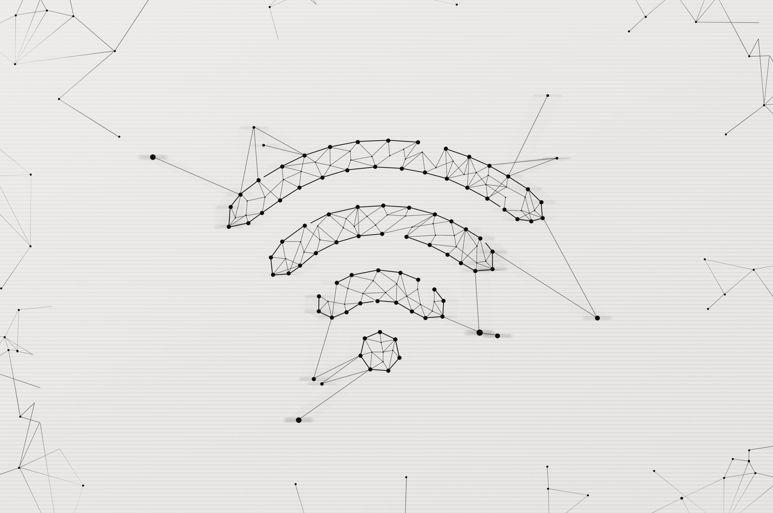
From Signals to Reality: Why WiFi-Based Occupancy Sensing Falls Short of Scientific Measurement Standards
Read More
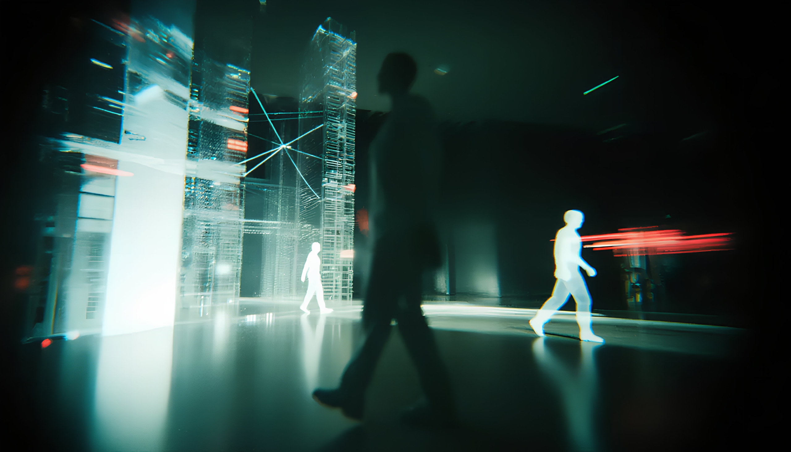
Beyond the Static Shell: Restoring Agency with Intrinsic Anonymity
Read More
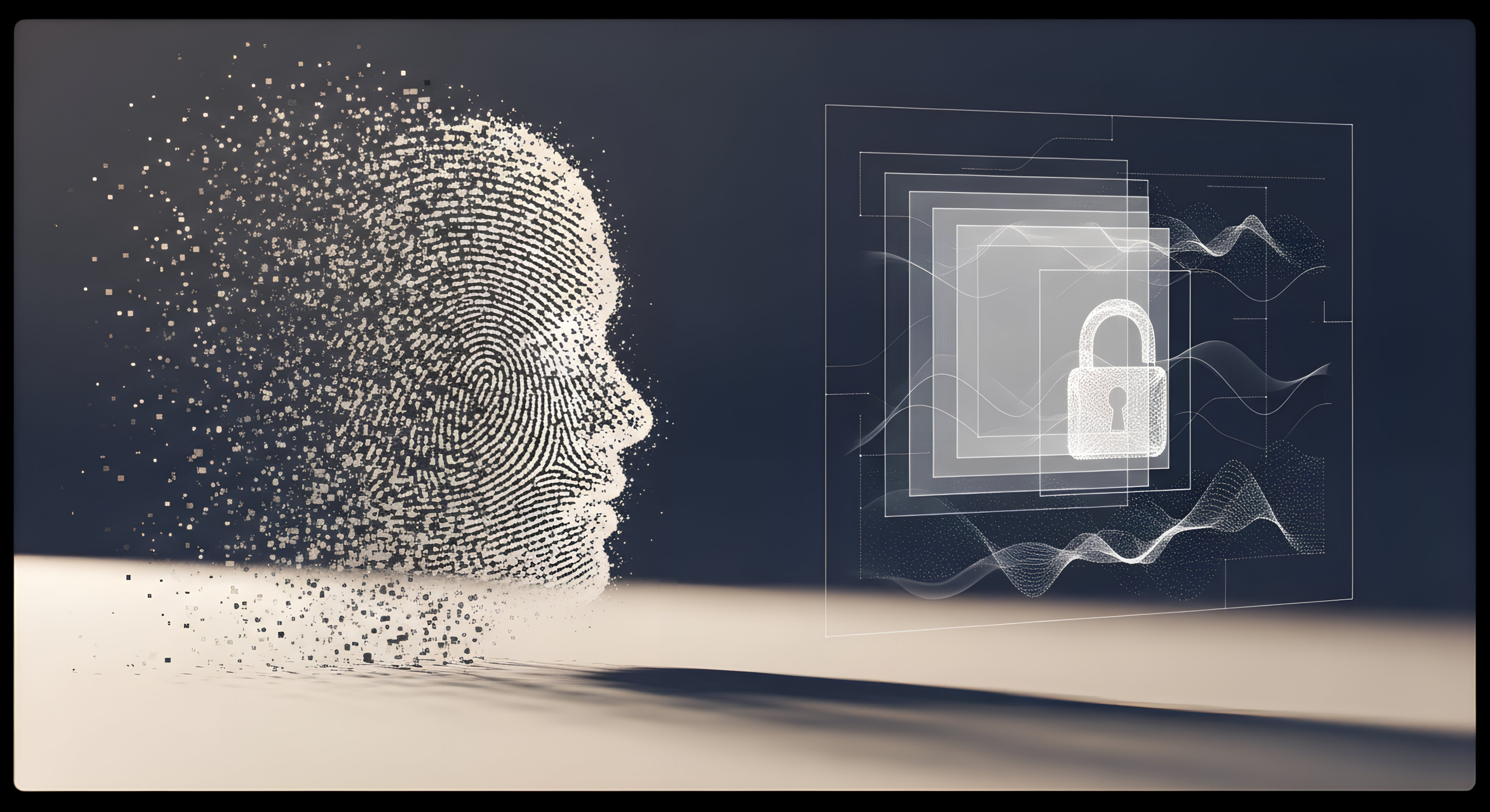
The Privacy Paradox in People Counting: Why RGB-Based AI and Stereovision May Fall Short of Modern Compliance Standards
Read More
The Multi-Million Euro Opportunity: How Universities Are Funding Research by Optimizing Real Estate
Read More
Beyond the Square Meter: Why the Future of Trade Shows Looks Like Google Ads
Read More
People Flow vs. People Occupancy: Choosing the Right “Engine” for Your Smart Building
Read More
Smart Campuses: The Invisible Sensors Optimizing University Spaces
Read More
The Infrastructure Moment: Why People Counting Is the Missing Link in the $106 Trillion Macroeconomic Game
Read More
How the EU AI Act Will Reshape the People Counting Market
Read More
Posts pagination
1
2
…
11
Next
Posts pagination
1
2
…
11
Nächste
Posts pagination
1
2
…
11
Suivant
FILTERS
FILTERS
Filtres
Filters
Filters
Search
×
Products
Use cases
Technology
Events
Privacy
Max Ruffo
Show
(
106
)
Cancel